
Technical guide
VFD Wiring Basics: Power, Motor, Control, Grounding and Commissioning
Understand the major VFD power and control connections, cable separation, grounding, shielding, protection and pre-start checks.
Jack Dean writes practical VFD selection, wiring, replacement and power-quality guides using current manufacturer documentation and explicit procurement checks.
Author profile
Correct VFD wiring is a system-design task, not a matter of matching a few terminal letters. The installer must coordinate the supply, disconnect and protective devices, drive, motor cable, grounding, controls, enclosure and machine-safety circuit. If you are still defining the equipment, complete the VFD selection process before finalizing the drawing; for fundamentals, see what a VFD does.
This guide explains the usual architecture of a low-voltage AC drive installation. It is not a substitute for the exact drive manual, approved drawings, lockout/tagout procedure or local electrical code. VFD DC-bus capacitors can retain hazardous voltage after input power is removed. Only qualified personnel should install or service the equipment, and they must wait for the manufacturer's stated discharge time and verify absence of voltage with an appropriate instrument.
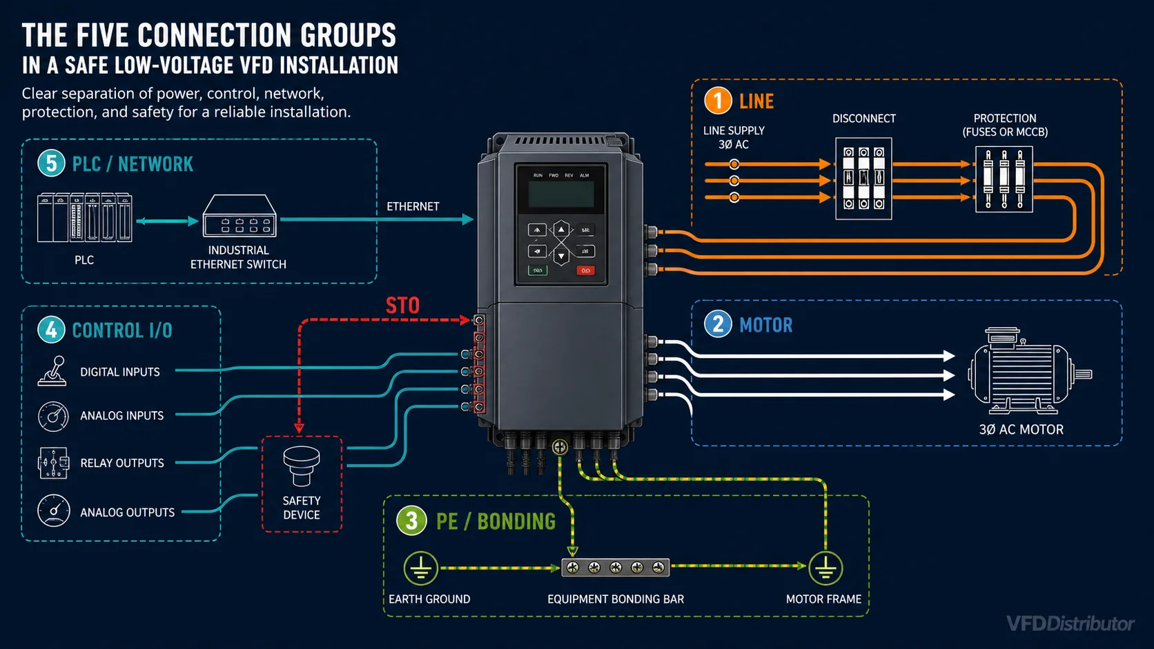
The five connection groups
Most installations can be understood as five separate groups:
- Line-side power: supply, disconnect, branch/short-circuit protection and optional input equipment.
- Motor-side power: VFD output, motor cable, motor earth connection and optional output equipment.
- Control I/O: start/stop, direction, permissives, interlocks, speed reference and status signals.
- Communications: serial or Ethernet-based industrial network.
- Protective bonding and shielding: PE conductors, equipotential bonding, cable screens and enclosure bonding.
Keeping these functions conceptually and physically separated prevents many nuisance trips and EMC problems.
Typical terminal names
Terminal markings vary, so the manual always wins. Common conventions include:
| Function | Common markings | Important note |
|---|---|---|
| AC input | R/L1, S/L2, T/L3 | Connect the supply here, never to motor-output terminals |
| Motor output | U/T1, V/T2, W/T3 | Connect only to the motor circuit and approved output devices |
| Protective earth | PE or earth symbol | Bond the drive and motor frames as specified |
| DC bus / braking | DC+, DC−, P, N, BR, B1/B2 | Hazardous internal bus; exact function differs by series |
| Digital input | DI, X, LI | Logic type and internal/external supply must match the parameter setup |
| Analog input | AI, AVI/ACI, COM | Confirm voltage/current mode and signal common |
| Relay output | RO, R1A/R1B/R1C | Dry-contact rating and normal state vary |
| Communication | RS-485, D+/D−, RJ45, fieldbus port | Follow the protocol-specific topology and termination rules |
Never infer a terminal function from a similar-looking drive. For example, the same label can represent different DC-bus or braking connections across brands.
Line-side power wiring
The usual sequence is:
Supply → disconnect/isolator → coordinated short-circuit protective device → optional contactor/reactor/filter → VFD input
The design must confirm:
- Supply voltage, phase and frequency are within the exact drive rating.
- Available fault current does not exceed the drive assembly's short-circuit rating when used with the specified fuse or breaker.
- Cable ampacity, temperature rating and termination method meet the manual and local rules.
- Fuse or breaker type and maximum rating follow the manufacturer's table.
- The disconnect provides the required isolation and is accessible or lockable as required.
- An upstream contactor, if used, is controlled for isolation or emergency architecture—not repeatedly cycled as the normal start/stop command unless the manufacturer permits it.
Use the drive's control terminals or network command for routine operation. Repeatedly opening and closing the input contactor can shorten precharge-component life, and disconnecting input power does not create a controlled motor stop.
An input AC reactor, DC choke, EMC filter or isolation transformer may be required by supply conditions or system objectives. These devices have different purposes. Select them from a power-quality and EMC assessment rather than adding them interchangeably. The VFD harmonics and line-reactor guide explains the line-side distinctions.
Motor-side power wiring
Connect the drive output to the motor terminals according to the approved drawing. Key rules include:
- Do not connect utility power to U/T1, V/T2 and W/T3.
- Do not install power-factor-correction capacitors or surge capacitors on the VFD output unless specifically approved for inverter duty and the exact application.
- Avoid switching contactors or disconnects between a running VFD and motor. If output isolation or multi-motor selection is required, interlock the sequence according to the drive manufacturer.
- Verify the motor connection—such as star or delta—matches its nameplate and the VFD output-voltage class.
- Size the motor cable for current, installation method, voltage drop, high-frequency effects and code requirements.
- Keep the motor cable within the drive/motor/filter limits.
If the motor rotates in the wrong direction, isolate and verify the system before exchanging any two motor-output phases, or use a permitted direction parameter. Do not swap the drive's input phases expecting to change motor rotation.
Motor-cable length and output filters
PWM output pulses travel along the motor cable and can reflect at the motor terminals. Longer cable, faster switching edges, cable construction and motor characteristics can increase peak voltage and common-mode current. Possible solutions include:
- Reducing carrier frequency within permitted limits
- An output/load reactor
- A dV/dt filter
- A sine-wave filter
- Inverter-duty motor insulation
- Bearing-current mitigation or insulated bearings in suitable cases
These are not equivalent products. An input line reactor addresses the line side; a motor-side reactor or filter addresses different output phenomena. Use the drive manual's cable-length tables and the motor manufacturer's inverter-supply limits.
Protective earth, bonding and shielding
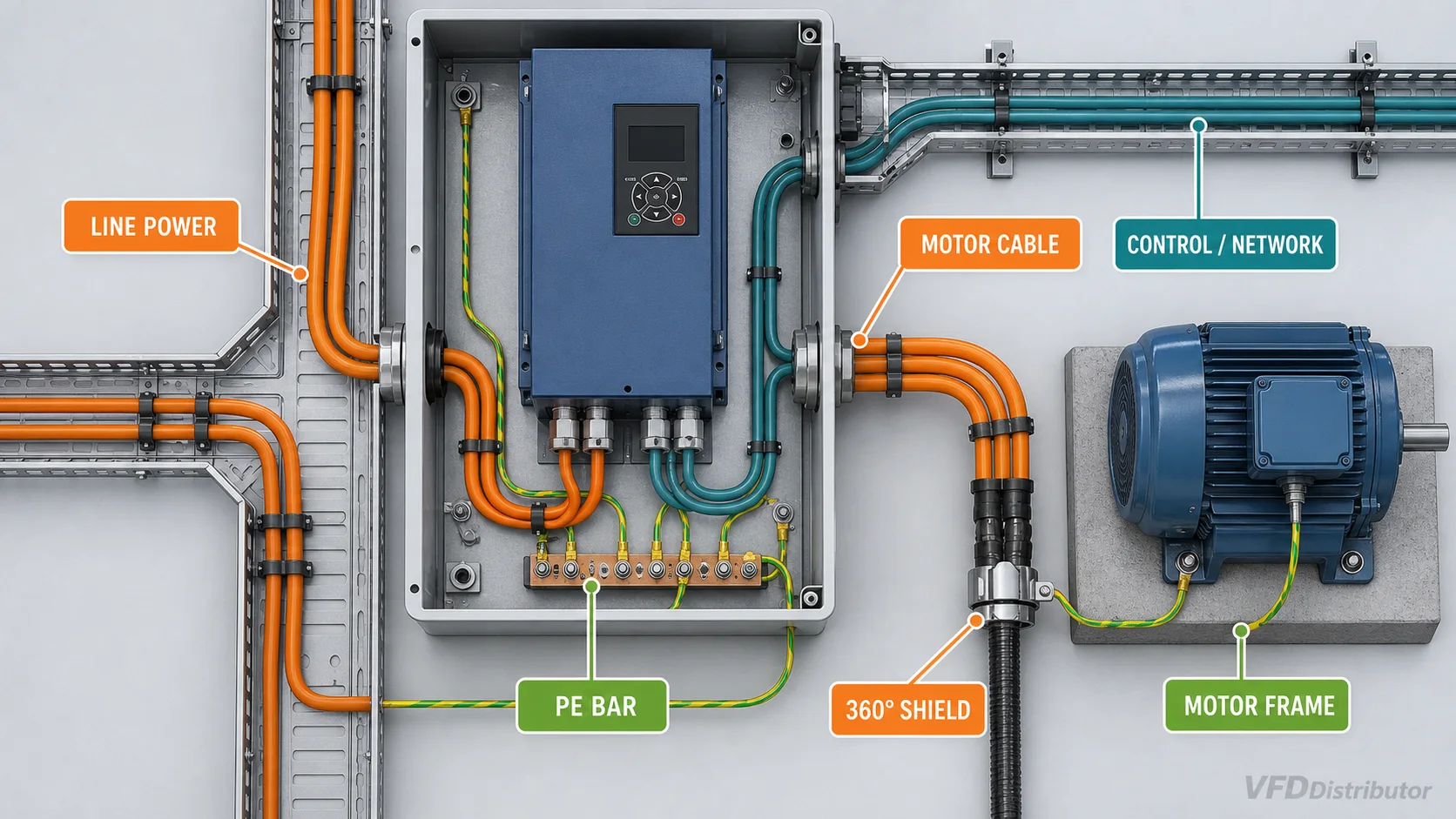
The VFD, enclosure, motor frame and associated exposed conductive parts require a low-impedance protective bonding path. High-frequency drive current makes physical layout important in addition to conductor cross-section.
Good practice, subject to the exact product instructions, includes:
- Bond the drive PE terminal directly to the designated protective-earth bar.
- Bond the motor frame through the required protective conductor.
- Remove paint or insulating finishes at designated bonding surfaces where specified.
- Keep bonding paths short and broad enough for high-frequency performance.
- Terminate motor-cable shields with the manufacturer-recommended gland or 360-degree clamp rather than a long pigtail when EMC performance requires it.
- Follow the drive and cable instructions for shield termination at the drive and motor ends.
Do not treat a cable shield as an automatic substitute for the required protective-earth conductor. Control-cable shield rules can differ from motor-cable rules and from one signal type to another; follow the exact drawing rather than a universal “ground one end” slogan.
Separate power, control and communication wiring
Route the incoming line cable, VFD output cable, low-level analog signals and communications in separate wiring zones or trays as required by the manual. Avoid long parallel runs between motor leads and signal cables. When crossings are unavoidable, a near-right-angle crossing reduces coupling.
Twisted shielded cable is commonly specified for analog references and differential serial communications. Keep the unshielded length at terminations short. Use the specified network cable, topology, shield and end-of-line termination for RS-485 or fieldbus systems; star wiring may be unsuitable for a bus designed as a daisy chain.
Start/stop and speed-reference wiring
A basic hardwired control might use:
- A maintained or momentary start/stop circuit on digital inputs
- A safety or process permissive
- A 0–10 V or 4–20 mA speed reference
- A relay output for run, ready or fault status
But the wire alone does not define behavior. Parameters determine whether inputs use two-wire or three-wire logic, source/sink polarity, normally open or normally closed interpretation, and which command source has priority.
For a 4–20 mA loop, confirm whether the signal is active or passive and which device supplies loop power. For a potentiometer reference, use the drive's reference supply only within its stated current limit. Avoid connecting commons from unrelated supplies without checking isolation and grounding.
Emergency stop and Safe Torque Off
A standard stop input is normally a control command, not a safety function. An emergency-stop design must come from the machine risk assessment and meet the required safety architecture.
Safe Torque Off (STO), when correctly implemented on a suitable drive, prevents torque-producing energy from being applied to the motor. It does not necessarily remove line or DC-bus voltage, provide electrical isolation, apply a mechanical brake, or guarantee that a rotating load stops immediately. Gravity and inertia can keep the machine moving. Use certified components, validated wiring and the product safety manual.
Braking resistor and DC-bus connections
Fast deceleration, high inertia or an overhauling load can raise DC-bus voltage. Depending on the drive, the system may need an internal or external braking chopper and a correctly rated resistor, or a regenerative solution.
Never connect a resistor by terminal-name guesswork. Confirm:
- Whether the chopper is built in
- Exact resistor terminals
- Minimum permitted resistance
- Continuous and peak power/duty cycle
- Thermal switch and fire-clearance requirements
- Cable type, protection and routing
Braking resistors can reach very high surface temperatures. Mount them so heat does not recirculate through the VFD or expose nearby materials and personnel.
Pre-energization checklist
Before applying power, document and verify:
- Correct drive and motor ratings
- Supply connected to input, motor connected to output
- Tightening torque and conductor preparation for every power terminal
- Protective earth and enclosure bonding
- No short circuit between phases or to earth
- Motor insulation test completed using the drive/motor manufacturer's procedure, with sensitive electronics disconnected as required
- Shield termination and cable separation
- Correct fuse/breaker and disconnect
- Control voltage and digital-input logic
- STO/safety circuit tested under the validation plan
- Mechanical readiness, guards and safe direction of rotation
- Cooling clearances, fan path and enclosure temperature
- Motor nameplate data and safe acceleration/deceleration limits entered
Photograph terminal layouts and record cable labels before covers are installed. That small step makes future fault-finding and replacement much faster; the same evidence becomes the starting point for a controlled VFD replacement.
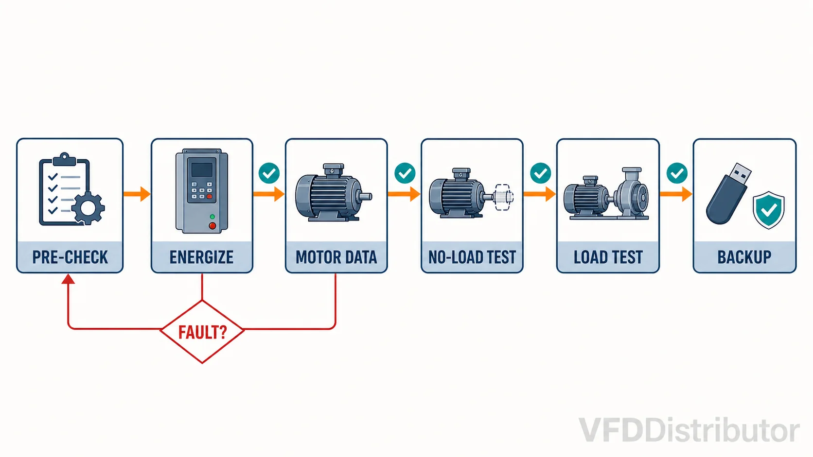
First commissioning sequence
- Keep the machine unloaded or mechanically safe where the application permits.
- Enter exact motor nameplate data.
- Select the control mode and perform the manufacturer-approved motor identification or autotune.
- Verify command source, speed reference, digital inputs and safety circuit.
- Jog at low speed and confirm direction.
- Check motor current, noise, vibration and cooling.
- Test acceleration, deceleration and stopping without exceeding mechanical or DC-bus limits.
- Test interlocks, loss-of-signal behavior, fault reset and communication-loss response.
- Run under representative load and record baseline current, DC-bus, temperature and process values.
- Save a parameter backup and the final approved drawings.
Frequent wiring mistakes
- Reversing input and output power terminals
- Omitting the motor or drive protective-earth connection
- Running encoder or analog cable beside motor leads
- Using a control stop as the only emergency-stop measure
- Installing capacitors on the drive output
- Switching the output while the VFD is producing voltage
- Applying a megohmmeter through the connected VFD electronics
- Assuming every RJ45 socket is Ethernet
- Copying parameters or terminal behavior from another model
- Forgetting that DC-bus voltage remains after the display turns off
Technical references
- Rockwell Automation PowerFlex 40P User Manual: installation, wiring and grounding
- Rockwell Automation PowerFlex installation instructions: grounding and shield termination
The examples above describe common architecture only. Before purchasing cable or protective equipment, obtain the manual for the complete drive catalog number, the motor data and the applicable project drawings. For an engineered enclosure, compare the available VFD panel solutions. For help matching the drive, motor and accessories, send the details through WhatsApp.