Motor current before nominal kW
Use the motor nameplate current as the final sizing check. The same kW motor can draw different current at different voltages and efficiency classes.
 WhatsApp
Variable frequency drive selection
Find a variable frequency drive that matches the motor, supply and load—not just the kW printed on the label. We support new installations, replacement projects and multi-brand sourcing from fractional horsepower through large industrial drive systems.
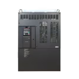
Selection foundation
A VFD changes the frequency and voltage supplied to an AC motor so speed and torque can be controlled. Correct selection depends on rated motor current, input supply, overload duty, acceleration time, ambient conditions and the control signals already used by the machine. For a replacement, dimensions, I/O, communications and braking arrangements also need to be checked before an alternative is approved.
Use the motor nameplate current as the final sizing check. The same kW motor can draw different current at different voltages and efficiency classes.
Pumps and fans often use normal-duty ratings, while conveyors, mixers and crushers may require a higher overload rating and more current margin.
Confirm analog signals, digital I/O, encoder feedback, PID functions and protocols such as Modbus, Profinet or EtherNet/IP.
Enclosure, temperature, altitude, cable length, EMC requirements and line quality can change the drive, reactor and filter package required.
Video introduction · 3:09
A concise visual introduction to how a variable frequency drive controls an AC motor and where VFD technology fits in an industrial system.
Video by Invertek Drives
VFD fundamentals
A VFD is more than an electronic speed dial. It converts fixed-frequency incoming power into a controlled three-phase output, then adjusts frequency, voltage and switching pattern to produce the motor speed and torque the process requires. The four explanations below connect the motor physics to the power electronics and the real application.
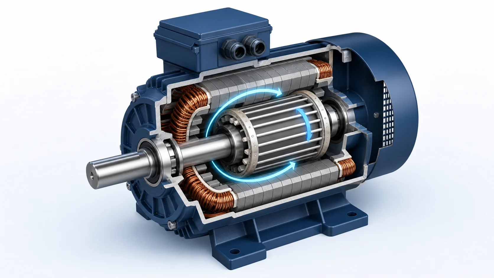
01 · Motor principle
In a three-phase induction motor, current in the stator windings creates a rotating magnetic field. Its synchronous speed is determined by supply frequency and the number of motor poles: Ns = 120f/p. A four-pole motor on 50 Hz power therefore has a 1,500 rpm synchronous speed; the rotor turns slightly slower when it is producing torque.
That difference is called slip. Relative movement between the rotating field and the squirrel-cage rotor induces rotor current, and the interaction of the two magnetic fields produces torque. By changing output frequency, a VFD changes the speed of the stator field and gives the motor a controllable operating speed instead of tying it directly to the utility frequency.
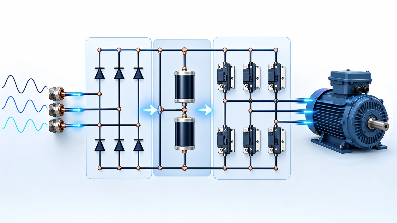
02 · Power conversion
Most conventional low-voltage VFDs use three functional power sections. The input converter rectifies AC into DC. The DC-link capacitors smooth the rectified waveform and create an energy buffer. The inverter then switches that DC bus onto the three motor phases in a carefully timed sequence.
The exact hardware varies. A small drive may use a diode bridge, while regenerative or low-harmonic systems can use an active front end. The selection consequence is important: the VFD input current, harmonic behavior and ability to return energy are not defined by the inverter alone; they depend on the complete front-end and DC-bus design.
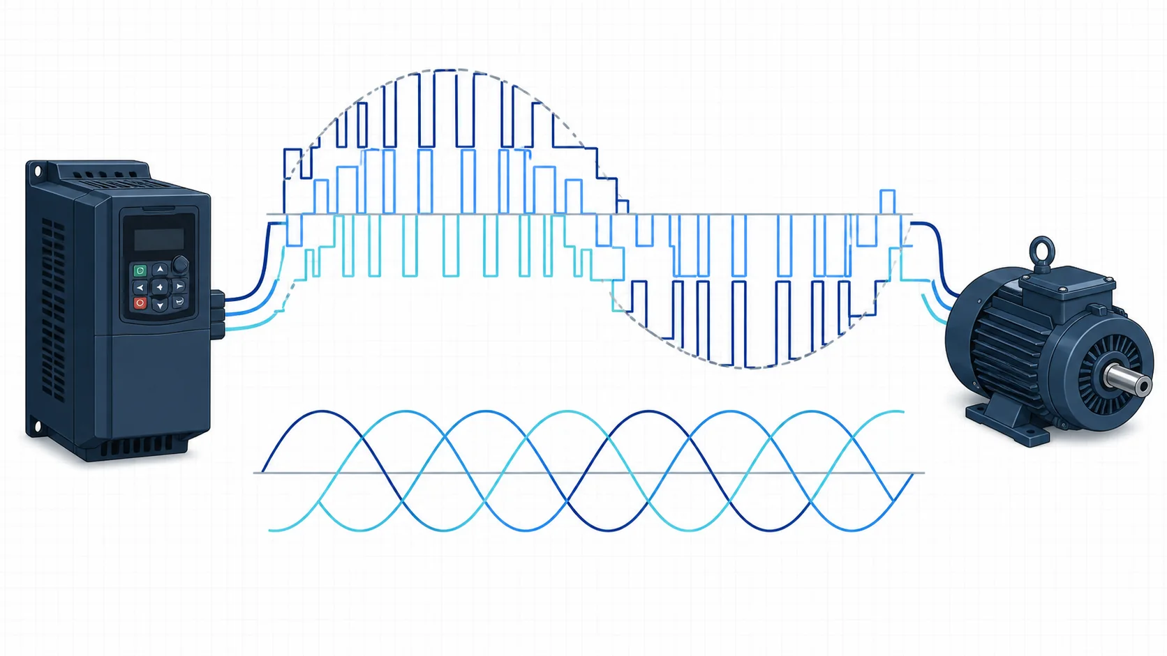
03 · PWM output
The inverter does not generate a perfectly smooth sine-wave voltage at its terminals. It uses pulse width modulation (PWM): the IGBTs switch the DC bus on and off rapidly, and the width and sequence of those pulses create the required fundamental three-phase voltage. Motor inductance filters much of the high-frequency content, so the phase current is far closer to a sine wave than the terminal voltage.
This distinction matters in an installation. Fast voltage edges can interact with long motor cables, motor insulation and grounding. Cable length, switching frequency, EMC rules and the motor’s inverter-duty rating determine whether a line reactor, output reactor, dV/dt filter or sine-wave filter should be considered.
04 · Application value
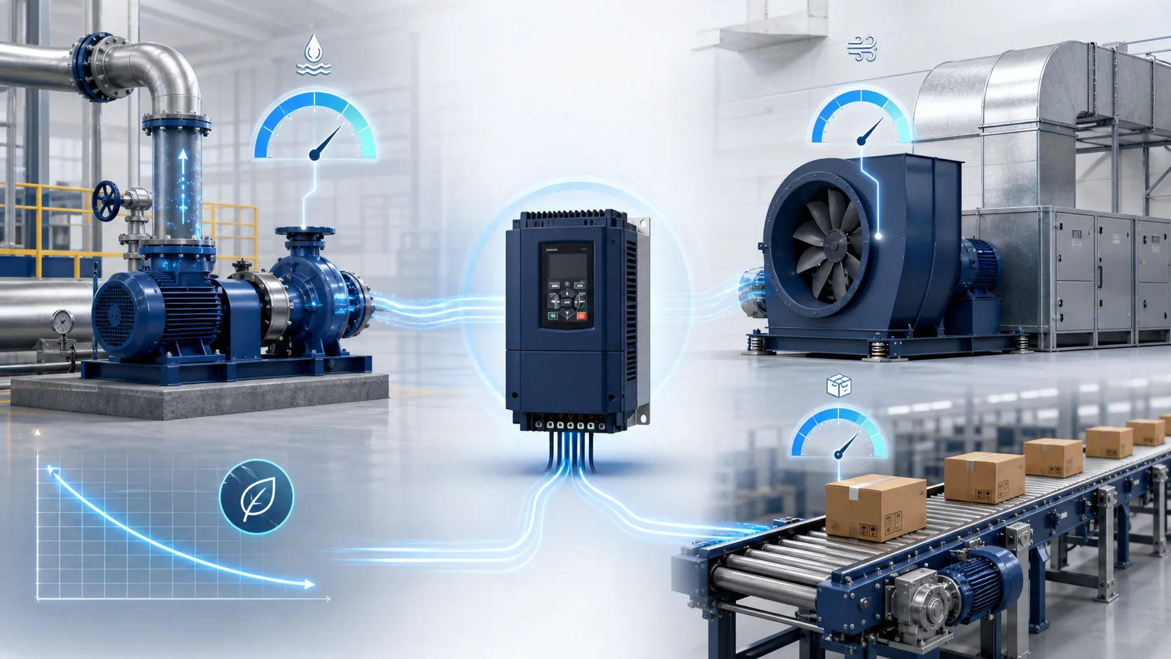
Pumps and fans are strong candidates because flow or pressure can often be controlled by reducing speed instead of wasting energy across a valve or damper. Conveyors benefit from adjustable line speed and gentler acceleration. Mixers, compressors and winding systems may use the drive for repeatable process control, torque management or coordinated motion.
The benefit must still be checked against the complete system. Energy savings depend on the load curve, operating hours, static head, mechanical losses and existing control method. A VFD can reduce starting current and mechanical shock, but it also introduces harmonics, high-frequency common-mode effects, heat and additional commissioning requirements. At sustained low speed, a self-cooled motor may need separate ventilation or temperature monitoring.
Product range
These groups are a practical way to narrow the requirement. Final model selection still depends on the electrical, mechanical and installation data shown on this page.
Browse VFD model reference librarySpace-efficient drives for small motors, simple machines and local speed control where the required I/O and overload duty are limited.
Typical fit: Small pumps, fans, conveyors and OEM equipment
Flexible low-voltage drives with common control modes, programmable I/O and communication options for everyday industrial loads.
Typical fit: Plant utilities and standard machinery
Variable-torque products with PID, sleep, multi-pump and building-control features selected around the hydraulic or airflow system.
Typical fit: Water systems, HVAC and cooling towers
Higher torque accuracy, faster response and optional encoder feedback for demanding speed or torque-control applications.
Typical fit: Conveyors, winders, mixers and process lines
Drive systems designed for frequent returned energy or defined input-current performance, subject to a complete system review.
Typical fit: Cranes, test stands and high-cycling machinery
Engineered drive packages for large motors where voltage class, transformer arrangement, cooling and site integration require project-level selection.
Typical fit: Large pumps, fans, compressors and mills
Quick selection
Choose any known values. You can also send the page with no selection and add a model number or nameplate photo in WhatsApp.
Typical specification scope
Common applications
Variable-torque control, PID, sleep mode and building-management communication can reduce energy use and mechanical stress.
Starting torque, speed regulation, braking and overload capability are matched to the loaded conveyor profile.
Acceleration, minimum speed, current margin and process control signals are reviewed before the drive is selected.
We compare the original unit with a current-series successor and a compatible alternative, noting wiring or programming changes.
Decision guide
From requirement to quotation
Send the motor or existing drive label plus any known power, voltage and application details.
Current, duty, control method, communications and installation conditions are checked against available models.
The quotation identifies the proposed model, included accessories, availability and delivery basis.
Frequently asked questions
The minimum useful data is motor rated current, motor voltage, supply voltage and load type. For an exact replacement, also provide the existing model code, control wiring, communication protocol and any braking resistor or filter connected to it.
Horsepower or kW is a good starting point, but output-current capacity is the final check. Derating may be necessary for heavy overload, high ambient temperature, altitude, single-phase input or a high carrier frequency.
Often yes, provided the electrical rating, overload duty, I/O, communications, dimensions and motor-control method are compatible. We identify any wiring, parameter or enclosure changes before proposing the substitute.
No. The need depends on supply impedance, harmonics, cable length, EMC limits, nearby sensitive equipment and the drive manufacturer’s guidance. The accessory package should be selected for the installation rather than added automatically.
We include this page, your selected model or specifications, and a reference. You only add quantity and destination before sending.