
Technical guide
VFD Harmonics and Line Reactors: What They Do and When You Need More
Understand how VFD input harmonics arise, what a line reactor can and cannot fix, how it differs from a load reactor, and when a harmonic study is needed.
Jack Dean writes practical VFD selection, wiring, replacement and power-quality guides using current manufacturer documentation and explicit procurement checks.
Author profile
Most conventional VFDs are nonlinear loads. Their rectifier and DC bus draw input current in pulses rather than as a perfect sine wave. Those pulses contain harmonic currents that flow through the supply impedance and contribute to voltage distortion. For the underlying rectifier–DC-link–inverter architecture, start with what a VFD is and how it works.
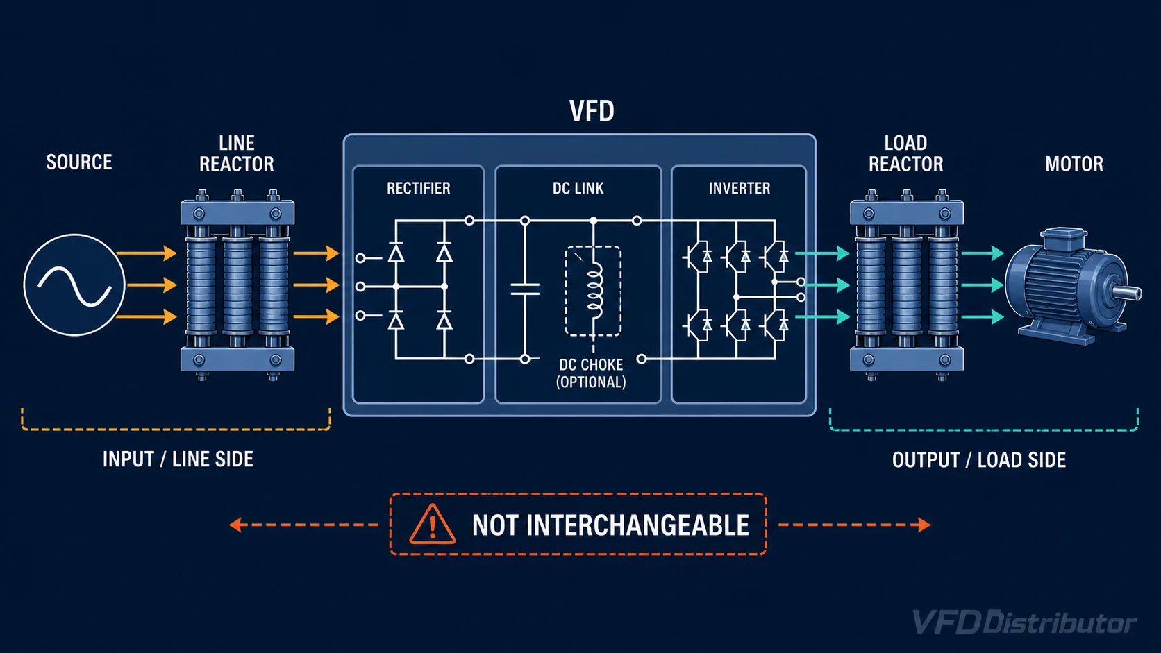
An input line reactor adds series inductive impedance ahead of the drive. It can reduce current peaks, moderate some harmonic current, and provide useful buffering against certain line disturbances. It is often a practical, low-cost component—but it does not make every installation compliant with a harmonic standard, and it is not interchangeable with an output reactor or harmonic filter.
This guide explains the distinctions engineers and buyers need before specifying equipment.
What are electrical harmonics?
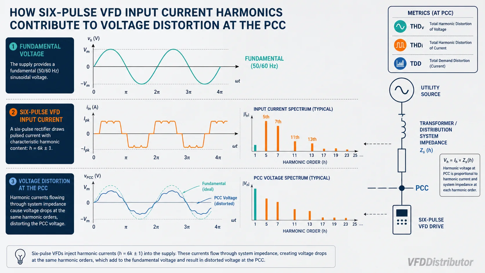
In a 50 Hz system, harmonic frequencies occur at integer multiples of the fundamental: 100 Hz is the second, 150 Hz the third, 250 Hz the fifth and so on. In a balanced three-phase six-pulse VFD, the characteristic input-current harmonics are typically around orders 5, 7, 11, 13 and higher, though the real spectrum depends on the circuit, source impedance, load and other equipment.
The drive injects harmonic current. As that current passes through transformer, cable and source impedance, it creates harmonic voltage distortion. The result seen at one point in the system is therefore a property of both the nonlinear loads and the network.
Possible consequences of excessive distortion include:
- Additional transformer, cable and generator heating
- Higher RMS current and reduced usable system capacity
- Capacitor-bank stress or resonance
- Voltage waveform distortion affecting other loads
- Nuisance operation or measurement error in sensitive equipment
- Generator instability or poor drive performance on weak supplies
Not every distorted current waveform creates an operational problem. The correct question is whether distortion at the defined measurement point exceeds the project limit or creates unacceptable equipment stress.
THD, THDi and TDD are not the same
Common terms are often mixed together:
- Voltage THD (THDv): harmonic voltage content relative to the fundamental voltage at the measurement point.
- Current THD (THDi): harmonic current content relative to the fundamental current measured at that moment.
- Total demand distortion (TDD): harmonic current relative to the maximum demand load current defined for the assessment.
At light load, THDi can look high because the denominator—the instantaneous fundamental current—is small. TDD gives a different system-level perspective. A vendor's “low THDi” value at rated load and stated source impedance is not proof that a facility meets IEEE 519.
IEEE 519-2022 applies steady-state voltage and current distortion limits at the user's point of common coupling (PCC). The applicable current limits depend on system conditions, including the relationship between available short-circuit current and maximum demand load current. Project specifications may impose other standards or stricter contractual limits.
Why a standard six-pulse VFD distorts input current
In a basic diode-front-end drive, the input rectifier charges DC-bus capacitors mainly when instantaneous line voltage exceeds bus voltage. That creates relatively narrow current pulses around voltage peaks. A DC choke or AC line reactor spreads conduction over more of the waveform and reduces peak severity.
Drive topology matters:
- A six-pulse rectifier with little impedance generally has higher input-current distortion.
- A DC choke or input reactor provides moderate mitigation.
- Multi-pulse systems use phase-shifting transformers to cancel selected characteristic harmonics.
- Passive harmonic filters target a defined spectrum and operating range.
- Active harmonic filters inject compensating current for multiple nonlinear loads.
- Active-front-end or low-harmonic drives actively shape input current and may support regeneration, subject to their design.
No topology has one universal distortion number. Performance varies with load, voltage balance, source impedance, component tolerances and system interaction.
What an input line reactor does
A line reactor is a three-phase inductor installed in series between the supply and VFD input. Depending on its impedance and the system, it can:
- Reduce peak input current and moderate characteristic current harmonics
- Buffer the drive from some line notching or rapid voltage transients
- Reduce nuisance overvoltage trips associated with capacitor switching in some installations
- Add impedance when the drive is connected to a relatively stiff, large transformer
- Reduce stress on the input rectifier and DC-bus capacitors
- Improve current sharing where specifically engineered
Reactors are commonly described by percent impedance, often around 3% or 5% at rated current, but the correct value is manufacturer- and application-dependent. More impedance is not automatically better. It creates voltage drop, heat and reduced DC-bus voltage, which can limit motor voltage and torque near full speed.
What a line reactor does not do
An input reactor does not:
- Guarantee IEEE 519 or another system limit at the PCC
- Eliminate all current harmonics
- Correct a resonant capacitor-bank problem without analysis
- Protect the motor from long-cable reflected-wave voltage in the same way as a dV/dt or sine-wave filter
- Replace required short-circuit protection or an isolation transformer
- Automatically solve common-mode current, bearing-current or EMC emissions
- Convert a standard drive into a regenerative drive
It may be part of the answer, but a system result requires a system calculation or measurement.
Line reactor, load reactor and filter: know the location
| Device | Installed | Primary purpose | Not equivalent to |
|---|---|---|---|
| Input line reactor | Before the VFD | Add line impedance, moderate input current peaks/harmonics, buffer some disturbances | Output filter |
| DC choke | In the VFD DC link | Smooth rectifier current and moderate harmonics with lower line-side voltage drop in some designs | Isolation transformer |
| Output/load reactor | Between VFD and motor | Moderate motor-side current edges and support some cable applications | Input harmonic solution |
| dV/dt filter | VFD output | Reduce motor-terminal voltage rise rate and peak stress | Sine-wave filter |
| Sine-wave filter | VFD output | Produce a much more sinusoidal motor voltage waveform | Line reactor |
| Passive harmonic filter | VFD/group input | Reduce selected input-current harmonics | Universal across all loading without design |
| Active harmonic filter | Common bus/PCC area | Dynamically inject compensating harmonic current | Branch protection |
The same reactor hardware is sometimes marketed for line or load use, but voltage, current, switching-frequency, insulation and manufacturer approvals still have to match the location. The companion VFD wiring guide shows how those locations fit into the complete installation.
When an input reactor is commonly considered
A reactor may be justified when:
- The drive manual requires or recommends it for the available transformer size or low source impedance.
- The drive has no built-in DC choke and moderate harmonic improvement is useful.
- Capacitor switching or line transients cause DC-bus overvoltage events.
- The supply is subject to notching or disturbances from other converters.
- A generator or weak network needs additional impedance—but only after checking voltage drop and control stability.
- A project standard calls for a defined input impedance on six-pulse drives.
Do not add a reactor blindly when the drive already has significant built-in impedance, the supply voltage is low, or the application needs maximum motor voltage at rated speed. Check the complete impedance and voltage-drop budget.
3% versus 5% reactors
Percent impedance is approximately the reactor's voltage drop at rated current expressed as a percentage of system voltage under its defined conditions. A 5% reactor generally limits current and harmonics more than a 3% reactor, but also creates more fundamental voltage drop and heat.
Selection must account for:
- System voltage and frequency
- Drive input current, not just motor hp
- Reactor continuous current and overload
- Inductance tolerance and saturation performance
- Enclosure temperature and cooling
- Voltage drop at expected load
- Existing AC/DC impedance in the drive and transformer
- Short-circuit and insulation ratings
- Manufacturer compatibility and installation clearances
Avoid assuming that “5%” produces a fixed THDi. The resulting waveform depends on the rest of the system.
Source impedance: stiff grids and generators
A drive connected close to a large transformer may see high prospective short-circuit current and very low source impedance. An input reactor can add beneficial impedance and reduce rectifier stress.
A generator is different. It has higher and frequency-dependent source impedance, and voltage regulator response matters. Harmonic current can distort generator voltage more than it would on a stiff utility source. A reactor may reduce current distortion but also increase voltage drop. Generator, drive and reactor should be studied together across the expected load steps; oversizing the generator alone is not always an efficient solution.
Capacitor banks and resonance
Power-factor-correction capacitors and the supply inductance can create a resonant frequency near a harmonic order. Adding nonlinear load may then amplify current or voltage rather than merely add distortion.
Do not place conventional power-factor capacitors on a VFD output. For line-side capacitor banks, perform or obtain a harmonic/resonance review, especially when:
- Capacitors or detuned banks are being added or changed
- Fuses fail or capacitors overheat
- Voltage distortion changes sharply with switching stages
- A facility has many drives or other nonlinear loads
A line reactor on each drive may help reduce contribution, but it is not a substitute for checking system resonance.
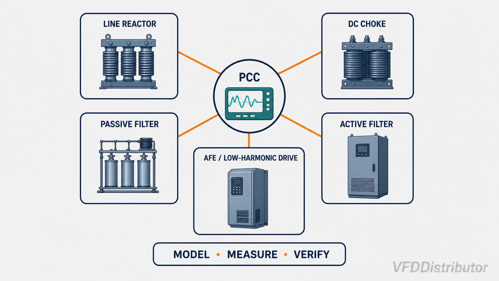
How to choose a mitigation method
Use the target, operating profile and network to choose—not a product slogan. Harmonic mitigation should be specified alongside the drive's current, duty and environment in the broader VFD selection process.
| Situation | Possible starting point |
|---|---|
| Few six-pulse drives, no strict PCC target | Built-in DC choke or 3–5% input reactor where the manufacturer supports it |
| Moderate drive concentration | Model aggregate TDD/THDv; compare reactors, DC chokes or passive filters |
| Many changing nonlinear loads | Consider a centrally sized active harmonic filter after measurements/study |
| Strict low-distortion requirement on each drive | Compare low-harmonic/active-front-end or suitably engineered passive-filter packages |
| Regenerative process | Regenerative drive/AFE may address energy flow and input current, but verify EMC and system behavior |
| Existing plant problem | Measure at the relevant points before choosing equipment |
The lowest-cost product is not always the lowest-risk solution. Include filter losses, footprint, cooling, resonance, maintenance, redundancy and performance at partial load.
Data needed for a harmonic study
Collect:
- One-line diagram and proposed PCC
- Utility or generator source data and available short-circuit current
- Transformer kVA, impedance, vector group and loading
- Cable/bus impedance where material
- Linear and nonlinear load schedule
- VFD topology, rating, built-in choke and expected load profile
- Capacitor banks and existing filters
- Operating combinations, diversity and expansion plans
- Required standard, project limit and measurement period
- Existing power-quality measurements, including loading when captured
For an existing facility, measurements should cover representative production states. A short snapshot taken when drives are lightly loaded can misrepresent worst-case TDD or voltage distortion.
Practical specification checklist
When requesting a reactor or harmonic solution, provide:
Supply voltage and frequency:
VFD complete model and input current:
Built-in AC/DC choke details:
Transformer/generator size and impedance:
Expected drive load profile:
Other nonlinear loads and capacitor banks:
Required PCC and standard/limit:
Existing THDv, THDi and TDD measurements with load:
Enclosure, ambient temperature and cooling:
Available footprint and bypass/redundancy needs:
This lets a supplier distinguish a simple power-quality accessory from a full study and mitigation package. Send the system information through WhatsApp for an initial equipment-path review.
Frequently asked questions
Does every VFD need a line reactor?
No. Some drives contain a DC choke or other input impedance; some installations have adequate source impedance and no harmonic target requiring more equipment. Other manuals require a reactor under defined transformer or supply conditions. Check the exact drive and system.
Will a 3% line reactor meet IEEE 519?
Not by itself as a general rule. IEEE 519-2022 limits are evaluated at the PCC, and the result depends on all loads, source strength and maximum demand current. A reactor can reduce one drive's contribution but cannot prove facility compliance.
Can I put the line reactor between the VFD and motor?
That location makes it an output/load reactor application. Even if the hardware appears similar, its purpose, rating and installation rules change. Obtain explicit manufacturer approval.
Is a line reactor the same as an isolation transformer?
No. A reactor adds series inductance but does not provide galvanic isolation or voltage transformation. A drive isolation transformer can also add impedance, but it has different cost, size, grounding and protection implications.
Technical references
- IEEE 519-2022: harmonic control at the point of common coupling
- Schneider Electric: Comparison of Harmonic Mitigation Solutions for VFDs
- Schneider Electric: Why some VFDs need an input reactor or DC choke
- Eaton: Harmonic Reduction Methods
Harmonic performance is system-dependent. Use current manufacturer data and a qualified power-system study when compliance, generator stability, capacitor resonance or critical-process reliability is at stake.