Line-side conditions
Supply voltage, available fault current, transformer size, existing capacitors and harmonic limits influence line-reactor and filter choices.
 WhatsApp
Drive-system protection and compliance
Match reactors, filters, braking components and protection to the actual drive system. We support accessory selection for supply harmonics, long motor cables, EMC concerns, regenerative energy and difficult electrical environments.
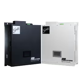
Selection foundation
A line reactor addresses different conditions from a load reactor, sine-wave filter or harmonic filter. Braking resistors handle regenerated energy during deceleration, while EMC filters address conducted emissions. Selecting by drive kW alone can produce incorrect impedance, current, voltage or thermal ratings. The one-line diagram, drive model, motor cable length, switching frequency and performance objective provide a much better starting point.
Supply voltage, available fault current, transformer size, existing capacitors and harmonic limits influence line-reactor and filter choices.
Cable length, motor voltage, insulation age and switching frequency help determine whether a load reactor, dV/dt filter or sine filter is appropriate.
Deceleration time, load inertia, cycle frequency and regenerated energy determine braking resistance, power and thermal duty.
Define the required harmonic, EMC or motor-terminal performance and the applicable standard instead of requesting a generic filter.
Product range
These groups are a practical way to narrow the requirement. Final model selection still depends on the electrical, mechanical and installation data shown on this page.
Input-side impedance used to moderate current waveform, supply disturbances and peak charging current under appropriate system conditions.
Typical fit: Drive inputs on stiff or disturbed electrical supplies
Output-side reactors applied to moderate motor-terminal waveform effects and support selected motor-cable installations.
Typical fit: Moderate cable extensions and motor protection support
Output filters with different degrees of waveform conditioning, losses, size and operating constraints.
Typical fit: Long cables, older motors and defined waveform limits
System solutions selected from drive load, network impedance, background distortion and the required measurement point.
Typical fit: Projects with documented harmonic-performance targets
Conducted-emission components coordinated with the drive, grounding, cable shielding and installation category.
Typical fit: Installations with defined electromagnetic-compatibility requirements
Dynamic-braking components sized from minimum resistance, regenerated energy, stopping time and cycle frequency.
Typical fit: Rapid deceleration and non-continuous regenerative duty
Quick selection
Select what is known and send the drive model or one-line diagram after WhatsApp opens. Unselected fields are not required.
Typical specification scope
Common applications
Line impedance, notching and transient exposure are reviewed before adding reactors or other input-side protection.
Cable length, motor insulation and allowable motor-terminal waveform guide the choice of load reactor, dV/dt or sine filter.
Cranes, centrifuges, conveyors and high-inertia machines may need dynamic braking or a regenerative drive solution.
Target limits, measurement point, system impedance and the total drive load are defined before a compliance solution is selected.
Decision guide
From requirement to quotation
Share the drive model, system voltage, motor cable, one-line diagram and the symptom or compliance target.
Input conditions, output waveform, braking energy and installation layout are separated so the right product class is considered.
The proposed component is checked for current, voltage, impedance, thermal duty, enclosure and connection location.
Frequently asked questions
A line reactor is installed on the input side of the VFD and can add impedance against supply disturbances while reducing current distortion. A load reactor is installed between the drive and motor, commonly to moderate output waveform effects and support longer cable runs.
These filters may be considered for long motor cables, older insulation, sensitive motors or applications with waveform limits. A sine filter provides stronger output smoothing but has different size, loss and operating constraints than a dV/dt filter.
Selection uses the drive manufacturer’s minimum resistance plus the load inertia, speed change, stopping time and cycle frequency. Both resistance and power or energy duty must be correct, and the resistor needs safe mounting and thermal protection.
Not automatically. IEEE 519 evaluation is made at the point of common coupling and depends on the complete system. Meeting a project limit may require system data, harmonic calculations or measurements and a dedicated filter or low-harmonic drive solution.
We include this page, your selected model or specifications, and a reference. You only add quantity and destination before sending.