
Technical guide
VFD Replacement Checklist: How to Replace an Obsolete or Failed Drive
Use this field checklist to identify an old VFD, select a compatible replacement, map wiring and parameters, and commission it with less downtime.
Jack Dean writes practical VFD selection, wiring, replacement and power-quality guides using current manufacturer documentation and explicit procurement checks.
Author profile
Replacing a VFD is rarely as simple as matching the kW or hp on the front label. A replacement must fit the motor current, load duty, supply, control method, I/O, communications, safety functions, enclosure, braking system and physical installation. It must also reproduce the machine's intended behavior—not merely make the motor rotate.
This checklist is designed for planned obsolescence projects and emergency failures. It helps a maintenance team collect the right information before ordering and gives engineering teams a controlled path through conversion and commissioning. Use the general VFD selection guide to validate current and duty, then apply this checklist to the migration details.
Work on energized drive equipment is hazardous. Follow the site's lockout/tagout process, the old and new product manuals, required discharge time and applicable electrical and machine-safety rules. Replacement and commissioning should be performed by qualified personnel.
First decision: like-for-like, successor or engineered retrofit?
There are three broad replacement paths:
| Path | Best when | Main risk |
|---|---|---|
| Exact catalog-number replacement | A current or verified spare is available and preserving configuration is valuable | Old stock condition, firmware/options and lifecycle support still require verification |
| Manufacturer-designated successor | The vendor supplies a migration guide, parameter converter or retrofit kit | Terminals, dimensions, option cards and parameter numbers may still change |
| Engineered cross-brand replacement | The original series is unavailable or a plant standard favors another platform | Requires complete functional mapping, panel changes and more commissioning |
“Direct replacement” should be treated as a claim to verify, not a synonym for “same power.” Even a successor can need a mounting adapter, new line reactor, different fuse, revised control voltage or PLC program change.
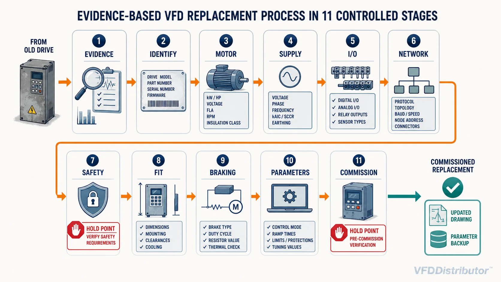
Stage 1: secure the machine and preserve evidence
Before removing the old unit:
- Record the machine, panel, asset number and date.
- Photograph the drive in place with covers closed.
- Follow safe isolation, wait the specified discharge time and verify absence of voltage.
- Photograph the full nameplate and every label.
- Photograph power, control, encoder, communication and option-card terminals before disconnecting anything.
- Mark every conductor at both ends; do not rely only on wire color.
- Record jumper, switch and termination positions.
- Save the PLC/HMI program and network hardware configuration if the drive participates in automation.
- Export drive parameters, fault history and firmware information when the failed drive still communicates.
- Record the operating symptom and events before failure rather than assuming the drive itself is the root cause.
A failed fan, seized pump, shorted motor cable, supply disturbance or overheated enclosure can damage the replacement too. Correct the system cause before installing new hardware.
Stage 2: identify the complete old-drive configuration
Collect more than the family name. Record:
- Manufacturer and complete catalog/type code, including suffixes
- Serial number and manufacturing date
- Firmware and hardware revision
- Input voltage, phase, frequency and input current
- Output voltage, continuous current and duty rating
- kW/hp rating under the actual normal- or heavy-duty table
- Enclosure/IP/NEMA rating
- Built-in EMC filter, DC choke or braking chopper
- Keypad/control-panel type
- Communication and feedback option cards
- Safety option or STO terminals
- External line/output reactors, filters, braking resistor and bypass equipment
Decode the full type code with the manufacturer's catalog or technical support. Two drives with the same front-panel series label can contain different power modules, filtering, network options or coated boards. If the original platform is no longer viable, the VFD manufacturer comparison can help build a cross-brand shortlist.
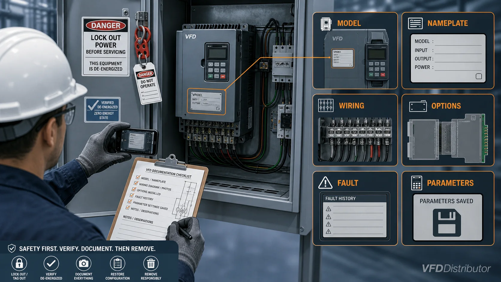
Stage 3: record motor and mechanical load data
From the motor nameplate and application, record:
- Motor type: induction, permanent magnet, synchronous reluctance or other
- Rated voltage, current, power, frequency, speed and power factor
- Connection arrangement and insulation/inverter-duty information
- Encoder/resolver type, supply, signal and pulses per revolution where fitted
- Motor cable type and route length
- Machine function and load characteristic
- Normal running speed and current
- Starting torque, loaded-start and jam conditions
- Acceleration, deceleration and stopping time
- Reversing, jogging, flying-start and catch-on-the-fly requirements
- Regenerative or overhauling behavior
- Minimum and maximum safe mechanical speed
Size the replacement from motor current, overload and real duty. An old drive may have been deliberately oversized, incorrectly sized or operating under a different rating convention. Do not copy its hp label without checking why it worked—or failed.
Stage 4: document the supply and protection
Confirm:
- Actual line voltage range, phase and frequency
- Grounding arrangement and available fault current
- Upstream transformer or generator size and impedance
- Disconnect, contactor, fuse and breaker catalog numbers and ratings
- Required short-circuit rating of the drive assembly
- Input line reactor, isolation transformer or harmonic equipment
- Power cable sizes, temperature ratings and termination space
- Facility EMC and harmonic requirements
The new drive manual may specify different fuses, breaker types or conductor sizes. A protection scheme approved for the old model does not automatically remain approved with a new one. Reassess any input reactor or filter using the guide to VFD harmonics and line reactors.
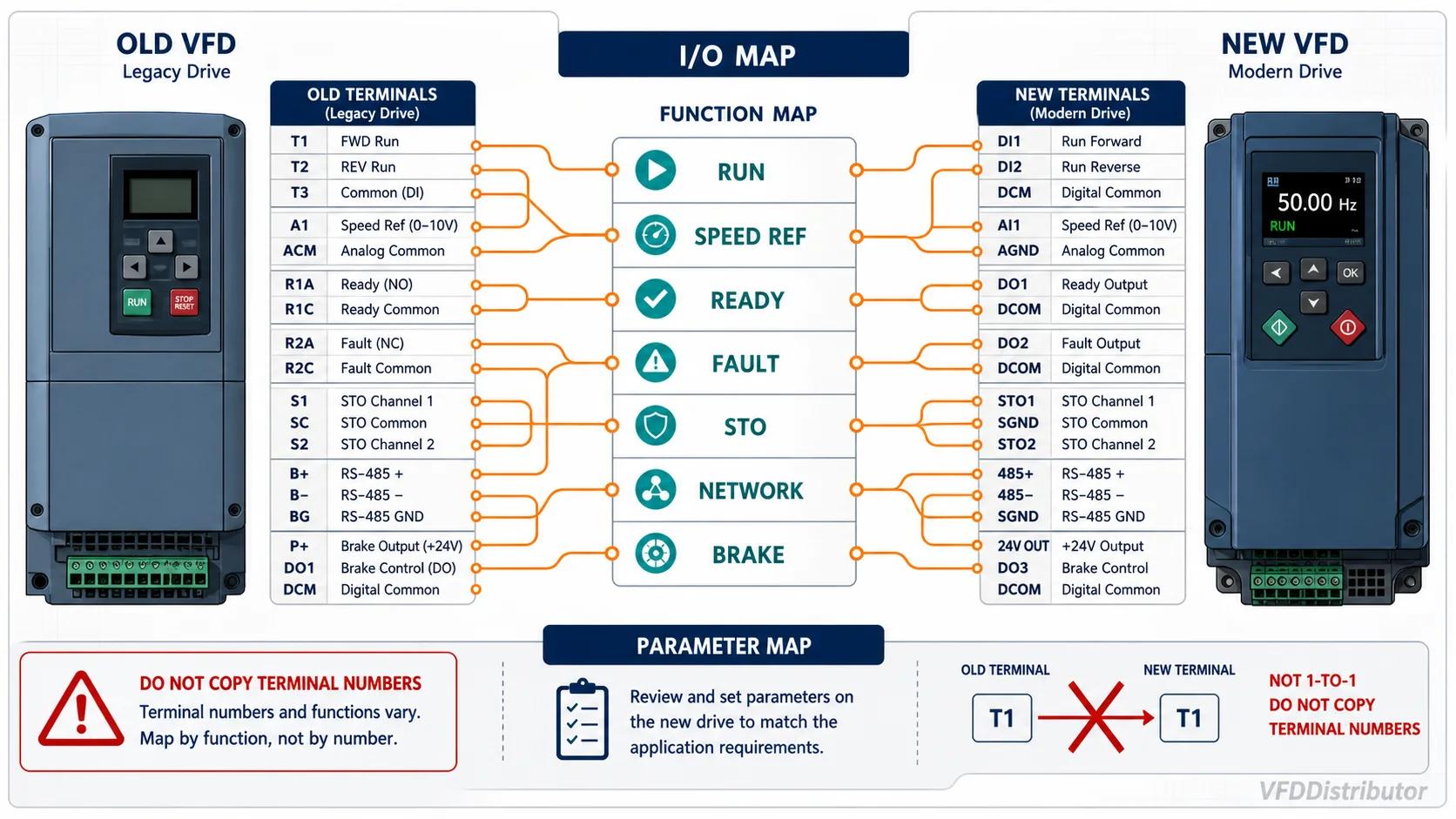
Stage 5: build an I/O and control-function map
Create a table before disconnecting wires:
| Old terminal / network signal | Electrical type | Machine meaning | New destination | New parameter / logic |
|---|---|---|---|---|
| Example: DI1 | 24 V digital input | Run permissive | DI2 | Assign “enable” |
| Example: AI1 | 4–20 mA | Speed reference | AI1 | Set current mode, scaling and loss action |
| Example: R1 | Relay contact | Drive fault | RO1 | Assign inverted fault status |
Map the function, not just the terminal number. Check:
- Two-wire or three-wire start logic
- Source/sink digital-input polarity
- Internal versus external 24 V control power
- Analog voltage/current mode, scaling, common and isolation
- Normally open/closed relay behavior and contact rating
- Thermistor/PTC or motor-temperature input
- Pulse/encoder supply and signal level
- Local/remote selector logic
- Interlocks, permissives and fault-reset behavior
- Process PID setpoint and feedback
- Loss-of-reference and communication-loss response
Test each function during commissioning. A motor that starts is not proof that the interlocks and fault responses are correct. Use the VFD wiring basics as a companion check for power, control, grounding and shielding.
Stage 6: verify communications and PLC integration
Record the exact protocol—not just “Ethernet” or “fieldbus”—and document:
- Network type and device profile
- Node address, IP settings and baud rate
- Option-card catalog number and firmware
- Input/output assembly or telegram type
- Control word, status word and process-data mapping
- Byte/word order and scaling
- Device description file or hardware catalog version
- PLC diagnostic logic and watchdog response
A successor may use a different device profile even when it supports the same physical network. Decide whether the new drive can emulate the old interface or the PLC/HMI program must change. Back up the working automation project before modification.
Stage 7: audit safety functions
Identify all safety-related behavior:
- Emergency stop category and machine stopping strategy
- STO channels, test pulses and feedback monitoring
- Safe brake control or other drive-based safety functions
- External safety relay or safety PLC
- Mechanical brake and load-holding requirements
- Restart prevention after power or communication loss
Do not bridge safety terminals simply because the replacement will not run. The required Performance Level or Safety Integrity Level belongs to the machine safety design and must be revalidated after the change. STO is not electrical isolation and does not by itself stop an already moving or gravity-driven load.
Stage 8: check physical and environmental fit
Measure and compare:
- Height, width, depth and mounting-hole pattern
- Required top, bottom and side clearances
- Airflow direction and heat loss
- Panel temperature, ventilation and cooling capacity
- Door/keypad cutout and cable entry
- Power-terminal location, conductor bend radius and lug size
- Weight and mounting-plate capacity
- IP/NEMA rating, contamination class, coated-board requirement and altitude
- Access to removable fans, capacitors and control terminals
A smaller modern drive does not guarantee an easier retrofit. Terminal locations can force cable extensions, and higher heat density can make the old enclosure unsuitable. Use an approved adapter plate or engineered mounting arrangement.
Stage 9: compare braking and motor-side equipment
Confirm whether the old system uses:
- Internal or external braking chopper
- Braking resistor value, power and duty cycle
- Regenerative unit or common DC bus
- Output reactor, dV/dt filter or sine-wave filter
- Motor contactor or bypass
- Multiple motors on one drive
- Long motor cable or inverter-duty motor
Never move a braking resistor onto unfamiliar terminals. The new drive's minimum resistance, transistor rating, duty model and protection can differ. Likewise, confirm that old output filters are compatible with the new switching frequency and drive family.
Stage 10: convert parameters by function
An uploaded backup can be valuable for a verified identical replacement, but do not blindly download an old parameter set into a different hardware or firmware revision.
Build a functional parameter sheet covering:
- Motor nameplate values and identification results
- Minimum/maximum frequency and direction limits
- Acceleration/deceleration and S-curves
- Current, torque and speed limits
- Control mode and carrier frequency
- Command and reference sources
- Digital/analog I/O assignments and scaling
- PID settings
- Flying start, automatic restart and catch behavior
- Braking and overvoltage control
- Skip frequencies and resonance avoidance
- Fault, warning and communication-loss actions
- Network process-data mapping
- Passwords, access levels and parameter locks
Use a manufacturer migration tool when available, but review the converted values. An automatically translated parameter set is still part of the commissioning design.
Stage 11: commission in controlled steps
- Perform a documented pre-power inspection.
- Energize with the motor mechanically safe and start inhibited.
- Confirm input voltage, drive status and control supply.
- Enter motor data and perform the approved identification routine.
- Verify STO/safety inputs and restart prevention.
- Check command and reference sources.
- Jog at low speed and confirm direction.
- Test every digital input, analog value, relay and network word.
- Run unloaded where possible; monitor current, DC bus, feedback and rotation.
- Apply load progressively and check acceleration, torque, braking and temperature.
- Trigger controlled test faults and communication loss to verify the intended response.
- Validate the machine safety functions under the approved test plan.
- Record final parameters, measurements and sign-off.
Keep the old drive available until the process has run through representative production conditions, provided site policy permits safe retention.
Emergency purchase information
When downtime is critical, send a supplier:
Complete old VFD model code and nameplate photos:
Motor nameplate photo and rated current:
Supply voltage and phase:
Machine/load and whether it starts loaded:
Normal running current and speed:
Control terminals and option-card photos:
PLC/network protocol:
Encoder and safety functions:
Braking resistor, reactor and filter details:
Enclosure dimensions and available space:
Destination and required delivery time:
This evidence is far more useful than “replace a 15 kW drive.” If the catalog number is incomplete, browse the VFD model catalog only as a starting point—final matching still requires the full configuration. Send the replacement package through WhatsApp for a cross-brand or current-series comparison.
Final handover package
Close the job with:
- Updated electrical schematics and cable/terminal schedule
- Final replacement bill of materials
- Approved drive parameter backup in both native and readable formats
- PLC/HMI backup and network configuration
- Safety validation record
- Baseline voltage, current, temperature and process measurements
- Commissioning and fault-response test results
- Photos of the completed installation and labels
- Recommended spare drive, fan, keypad and option-card information
The best replacement is one the next technician can understand and reproduce.
Technical references
- Siemens Retrofit Kits for Drives: configuration, parameter conversion and installation workflow
- Siemens SINAMICS Startdrive: drive parameterization and commissioning
Migration tools are product-specific. Verify the exact old and new catalog numbers, firmware, option cards and manufacturer documentation before using a converted configuration.